lv instrumentation diagrams | instrumentation loop diagram lv instrumentation diagrams Typically instrument abbreviations used in P&IDs consist of two letters: the first indicating the process variable and the second indicating the instrument/controller function. For example, the . LOUIS VUITTON Official USA site - Discover designer women's bags & purses from the world's top luxury Maison. Shop the latest collection of canvas and leather handbags.
0 · p&id instrumentation diagram
1 · instrumentation loop diagram
2 · instrumentation diagram abbreviation example
3 · instrumentation and control diagram
4 · industrial instrumentation diagrams
[Chore Quest] After reached Lv 50, players go to Waterfall Village to accept Chore Quest from Prophet Norton. Help the residents of Stars Land and enhance yourselves.Chore Quest has total 200 rounds, players try to accept the quest from 1st round to get rich Exp reward. 100th and 200th round have chances to get any rare items.

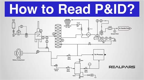
Typically instrument abbreviations used in P&IDs consist of two letters: the first indicating the process variable and the second indicating the instrument/controller function. For example, the . A P&ID could be a detailed flow diagram of the processing unit, ancillary unit, an offsite product storage system, product loading system, or it could be a drawing of the process .P&IDs and loop diagrams are construction and documentation drawings that depict the flow of the process and illustrate the instrumentation control and measurement interactions, wiring and . P&ID diagrams (Piping and Instrumentation Diagrams) provide a schematic representation of the functional relationship between piping, instrumentation, and system .
Definition: “A schematic diagram of the relationship between instruments, controllers, piping, and system equipment.” (Kirk, Weedon, & Kirk, 2014, p. 23) P&IDs are a symbol based schematic .To further understand instrument abbreviations used in instrumentation and process diagrams, we have presented more examples of the common combinations of instrument abbreviations you . The Process and instrumentation diagram, commonly known as a P&ID, shows the connections between process equipment. The diagram indicates the flow directions, safety .Learn How to Read Piping and Instrument Diagram-P&ID, Process Flow Diagram and Block Flow Diagram used in Process Plant.
Typically instrument abbreviations used in P&IDs consist of two letters: the first indicating the process variable and the second indicating the instrument/controller function. For example, the instrument abbreviation “PI” denotes a “Pressure Indicator”. A P&ID could be a detailed flow diagram of the processing unit, ancillary unit, an offsite product storage system, product loading system, or it could be a drawing of the process and instrumentation system that connects different operating facilities together.
p&id instrumentation diagram
P&IDs and loop diagrams are construction and documentation drawings that depict the flow of the process and illustrate the instrumentation control and measurement interactions, wiring and connections to the process. The process is illustrated in . P&ID diagrams (Piping and Instrumentation Diagrams) provide a schematic representation of the functional relationship between piping, instrumentation, and system components within a project. They offer a detailed overview of the process flow, including equipment, valves, and instrumentation, crucial for design and operational understanding.Definition: “A schematic diagram of the relationship between instruments, controllers, piping, and system equipment.” (Kirk, Weedon, & Kirk, 2014, p. 23) P&IDs are a symbol based schematic language that once understood, adds simplicity to the information being presented. They can also be confusing when a unique symbol appears.To further understand instrument abbreviations used in instrumentation and process diagrams, we have presented more examples of the common combinations of instrument abbreviations you may likely come across.
The Process and instrumentation diagram, commonly known as a P&ID, shows the connections between process equipment. The diagram indicates the flow directions, safety and control measures, and pressure ratings of a system through visual symbols.Instrumentation: The instrumentation includes sensors and other devices that measure process parameters like pressure, temperature, and flow rate. The information is used to provide feedback to the controller and ensure the desired flow rate is maintained.
Below Table 3 shows some instrument abbreviations for devices like switches, alarms, transmitters, solenoids, relays, primary elements, test points, probe, view glass, as well as final elements. What do Tag Numbers on P&ID Diagrams represent?Learn How to Read Piping and Instrument Diagram-P&ID, Process Flow Diagram and Block Flow Diagram used in Process Plant.Typically instrument abbreviations used in P&IDs consist of two letters: the first indicating the process variable and the second indicating the instrument/controller function. For example, the instrument abbreviation “PI” denotes a “Pressure Indicator”.
A P&ID could be a detailed flow diagram of the processing unit, ancillary unit, an offsite product storage system, product loading system, or it could be a drawing of the process and instrumentation system that connects different operating facilities together.P&IDs and loop diagrams are construction and documentation drawings that depict the flow of the process and illustrate the instrumentation control and measurement interactions, wiring and connections to the process. The process is illustrated in . P&ID diagrams (Piping and Instrumentation Diagrams) provide a schematic representation of the functional relationship between piping, instrumentation, and system components within a project. They offer a detailed overview of the process flow, including equipment, valves, and instrumentation, crucial for design and operational understanding.
Definition: “A schematic diagram of the relationship between instruments, controllers, piping, and system equipment.” (Kirk, Weedon, & Kirk, 2014, p. 23) P&IDs are a symbol based schematic language that once understood, adds simplicity to the information being presented. They can also be confusing when a unique symbol appears.To further understand instrument abbreviations used in instrumentation and process diagrams, we have presented more examples of the common combinations of instrument abbreviations you may likely come across.
instrumentation loop diagram
The Process and instrumentation diagram, commonly known as a P&ID, shows the connections between process equipment. The diagram indicates the flow directions, safety and control measures, and pressure ratings of a system through visual symbols.
Instrumentation: The instrumentation includes sensors and other devices that measure process parameters like pressure, temperature, and flow rate. The information is used to provide feedback to the controller and ensure the desired flow rate is maintained.

instrumentation diagram abbreviation example
instrumentation and control diagram
Projektā iesaistījās divi partneri – Nevalstiskā organizācija “Sprendimų centras” Lietuvā un biedrība Eiroreģions “Ezeru zeme” Latvijā, Krāslavā. Projekta “PRACTICAL ARTS” mērķis ir stiprināt Krāslavas un Dusetos pašvaldības, kā arī risināt problēmas, kas saistītas ar atkārtotu resursu izmantošanu .EZFORM LV 1827. $2,595.00. ($89.00 shipping) Buy Now. EZFORM ® LV 1827 VACUUM FORMING MACHINE $2595.00 ( US Lower 48 states $89.00 Shipping ) Lead Time 4-5 days. Specifications: Unit measures : 30 " high x 35 " long x 21 " wide. Plastic sheet size : 21 1/4 " up to 22 "x 30 1/4 " up to 31 " ( 6 pieces out of a standard 4 x 8 feet sheet )
lv instrumentation diagrams|instrumentation loop diagram


